Introduction
Our arms are considered one of the main limbs responsible for communicating and interacting with everything that surround us.They are the primary way of sensing and touching other things due to the numerous amount of neurons on every inch of your skin , that is why nobody can live a normal life without the presence of this crucial limb. Lots of people suffers from amputated limbs due to lots of reasons . For instance , people who have amputated limbs due to wars , diseases , or even ransradial amputation which is the most common one (a surgical procedure in which the radius and bones of the lower arm are cut removed from the body)
These people are being judged all the time and dealt with as if they are handicapped or as if they got some sort of a disability , tho they might have lost their limb for a reason which is out of their hand ! Human’s interaction with modern day technology might be able to save the situation , as nowadays we are able to read the EMG signal produced from the contraction of antagonistic pairs of muscles like the biceps and triceps [1] , which can be used to control a 3D printed model of a prosthetic arm , so that it act as an artificial arm to compensate the absence of missing arms for people suffering from amputations.
This Project gave me the privilege to do intensive research on the EMG signal to know how to extract such signal and by which device and how to send the signal from the Human’s arm to the 3D printed one.
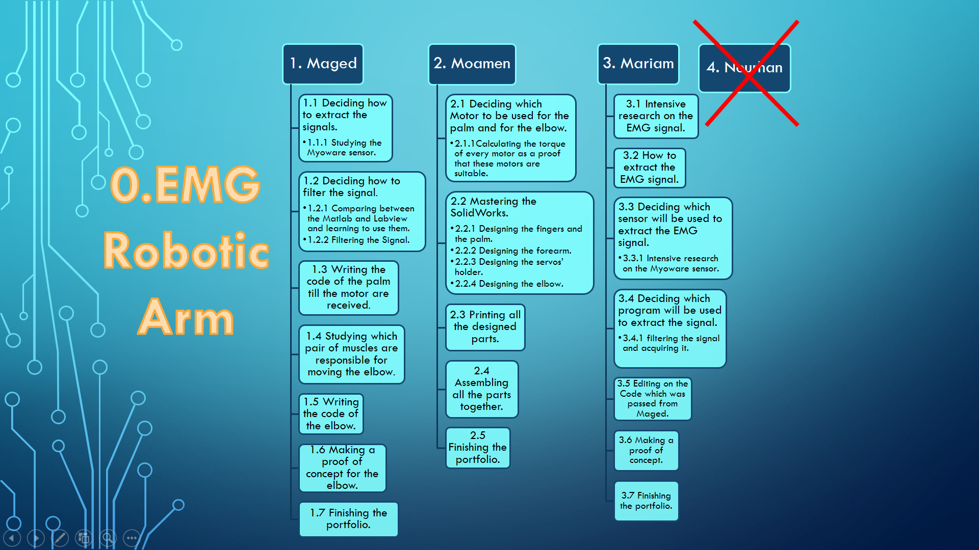
Work Break Down Structure for the project
Literature Review
Basically , the Humans’ muscles produce a various of signals when either contracted or relaxed , but the aim of my project is to control the EMG specifically as its easier to control the EMG than the rest of the signals like the EOG and EEG [2]. In addition to the cost of components needed , the sensors and the kit needed for the EMG is significantly cheaper than the ones for the other signals – In some other signals the cost can be doubled ! – Moreover , the EMG signal can be easily extracted, filtered and possessed that is what makes it ideal to be used in such a project.
To start with , the EMG signal fluctuates in the amplitude , meaning that if the muscle is contracting the signal’s amplitude will be at it’s peak , while it is relaxing , the muscle’s amplitude will be at it’s lowest[3]. Furthermore, differentiating between the moves of the human arm so that it would be copied on the artificial one is one of the limitations as differentiating between the movements would require more than one sensor to be placed on the skin or by injecting the muscle itself with Pentium iodide[4] which is hazardous without any members in our team studying biology or medications and unfortunately we were limited in the supplies of resources in making the project as some resources were shared among the groups so the option of getting more sensors was neglected as well.
The aim for this project is to create a prosthetic arm for amputee people for eliminate the discrimination they are suffering from , one of the goals is to create this arm with the lowest cost possible because simply what makes a project successful is maintaining it to work successfully using the cheapest reliable components.
Components Used
- Myoware Sensor
- Micro controller kit – Arduino Uno –
- MG90S Servo Motor – For the thumb –
- MG996R Servo Motor – for the rest of the 4 fingers –
- LD-20MG Servo Motor – for the elbow –
Myoware Sensor 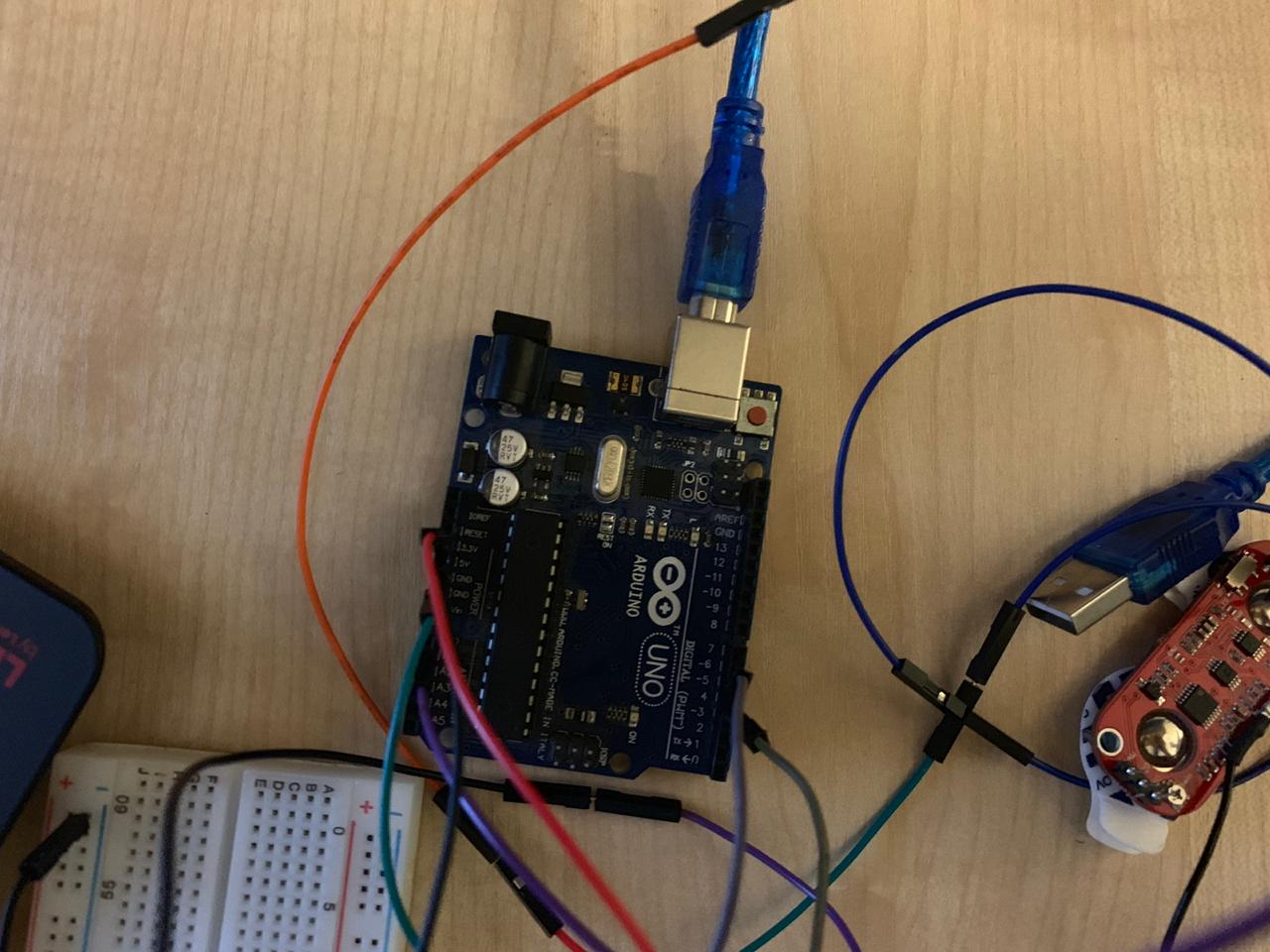
Arduino – Micro controller – 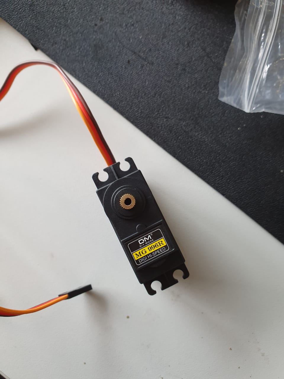
Fingers’ Servo Motor 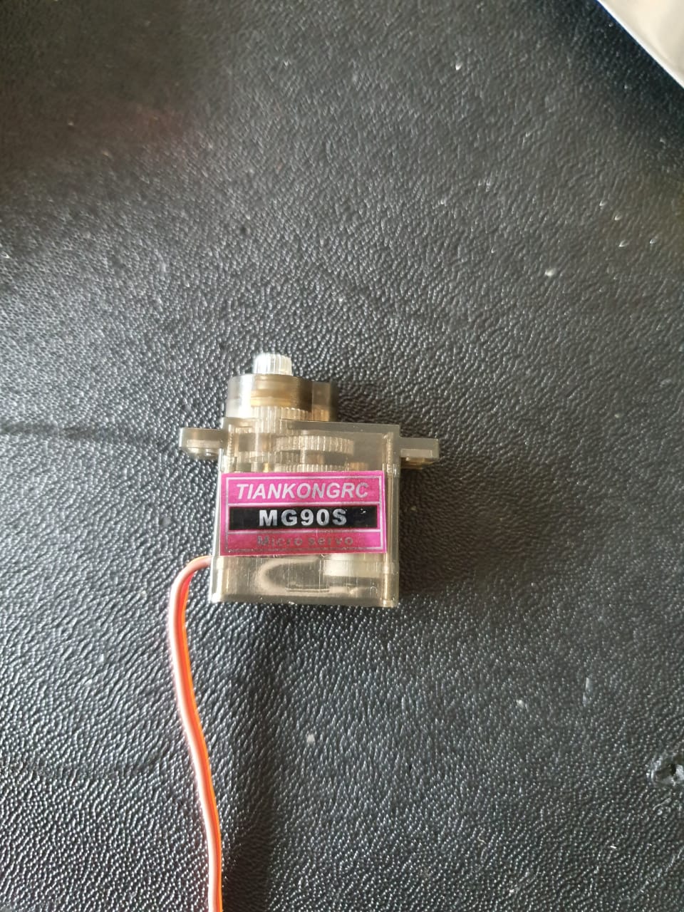
Thumb Servo Motor
Concept of Operation
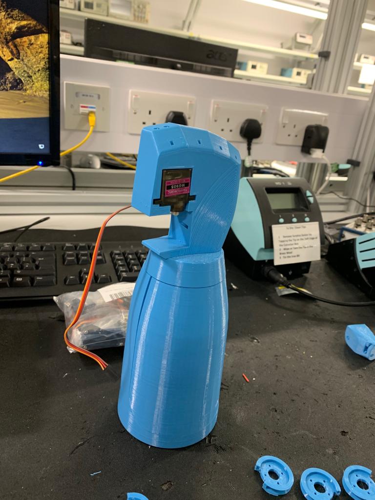
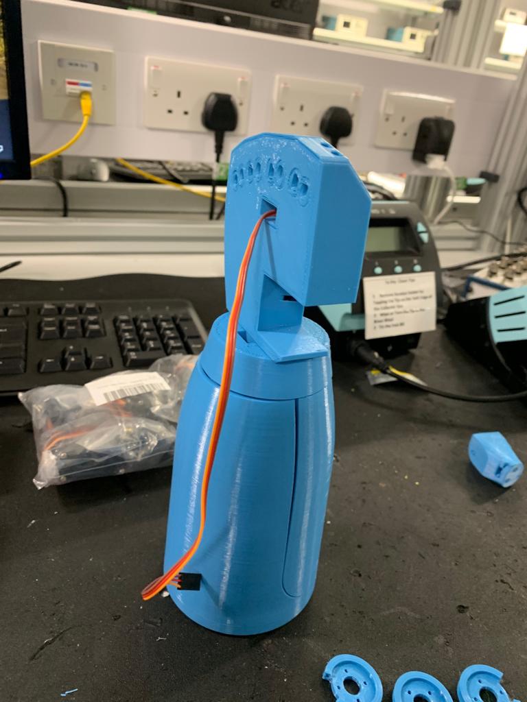
Simply , my project consists of 2 parts , first part was to control the 5 fingers of the palm , then after finishing this part I was assigned to control rotating the elbow by an angle of 90o in the last couple of weeks. Surely it was not easy because I was assigned to move the elbow to late so I had no time to do such an intensive research like the research I did for the palm and because there were financial difficulties getting the servo motor needed for the elbow – LD-20MG – Needless to mention my medical condition,as I stayed in the quarantine in Preston Royal Hospital for a while due to a bacterial infection and tuberculosis infection. However, the word ” Surrendering ” does not exist in my dictionary.
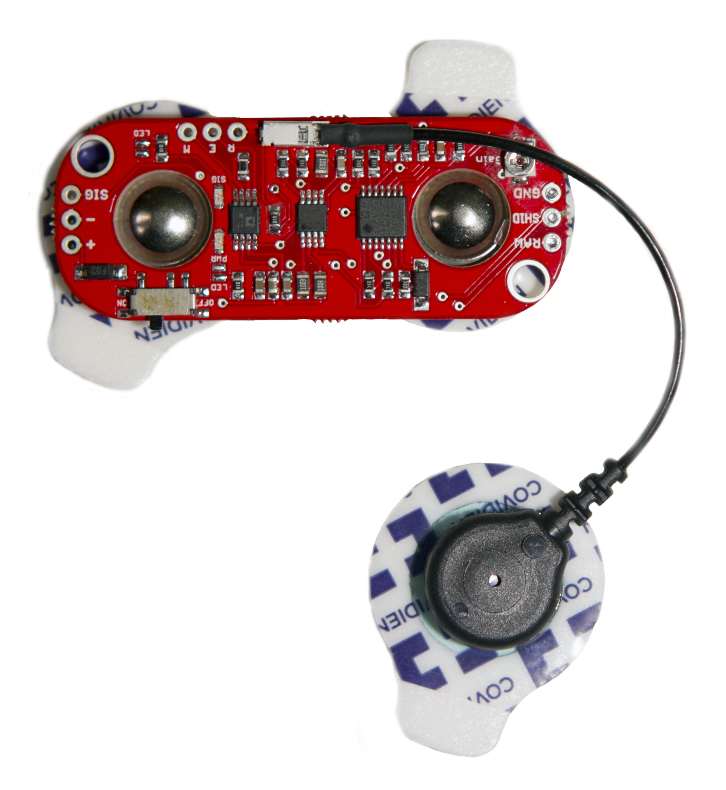
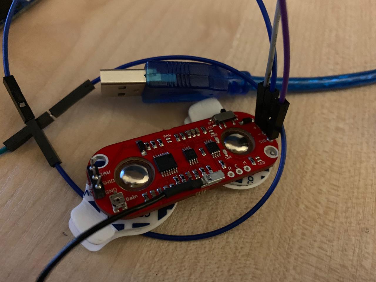
Fig 2.0 showing the Myoware sensor
Pololu – MyoWare Muscle Sensor [Internet]. Pololu.com. 2019 [cited 19 August 2019]. Available from: https://www.pololu.com/product/2732
Firstly, My first aim was to learn as much as possible about the Myoware Sensor as Measuring muscle activation via electric potential, referred to as electromyography (EMG), has traditionally been used for medical research and diagnosis of neuromuscular disorders. However, with the advent of ever shrinking yet more powerful micro controllers and integrated circuits, EMG circuits and sensors have found their way into Prosthetic, Robotics and other control systems. The sensor is used to read muscle activation signal, it is from Advanced technologies. It is suitable for producing raw EMG signal and Analog output signal for micro controller based application, this sensor designed for reliable EMG output with low power consumption[5].
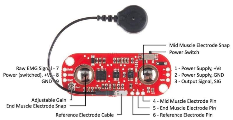
It operates with single power supply (+2.9V to +5.7V) with polarity reversal protection, additional feature in this sensor is that we can adjust the sensitivity gain.
Features
- Dimensions: 2.1″ × 0.8″ (excluding reference electrode cable, which is about 3″ long)
- Operating voltage: 2.9 V to 5.7 V (unlike previous sensor versions, no negative supply is required)
- Analog voltage output from 0 V to +Vs (supply voltage)
- Adjustable gain
- Both EMG envelope and raw EMG outputs available
- Embedded electrode connectors – electrodes snap directly into MyoWare (alternatively, external electrode cables can be connected)
- LED Indicators – one power LED, and one LED that brightens when the muscle is flexed
- Power switch
- Reverse voltage protection
- Two mounting holes (suitable for M3 or #4 screws)
- Informative user’s guide (1MB pdf)
MyoWare sensor internal structure
Coolcomponentscouk. Coolcomponentscouk. [Online]. Available from: https://coolcomponents.co.uk/products/myoware-muscle-sensor-development-kit %5BAccessed 19 August 2019].
Connection to the Microcontroller
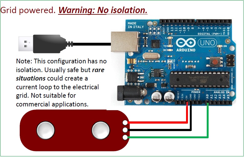
Theorycircuitcom. TheoryCIRCUIT – Do It Yourself Electronics Projects. [Online]. Available from: http://www.theorycircuit.com/myoware-muscle-sensor-interfacing-arduino/ %5BAccessed 19 August 2019].
Go back and edit info
Selection of Servo Motors
The servo Motors were chosen by our mechanical member Moamen Yehia, as for controlling the fingers a high torque servo motor was needed to be able to grip the fingers, pulling it onward the moment the forearm muscle contract. Same concerning the Thumb, a high torque Servo Motor was needed so that the thumb get pulled the moment the palm and the forearm contracts. Choosing the Elbow’s motor was not an easy thing because we needed a very high torque motor which is able to rotate the arm by ninety degree the moment the triceps contract , rotating the whole forearm and the palm as well. it is not impossible but it is hard , because such motor will be so expensive , luckily we found a cheap one which got a torque of 20 N.M which will be more than enough to rotate the whole arm.
Getting deeper into the Project
The first thing that was done after receiving the Myoware sensor was testing it on my arm to determine the threshold of my muscle’s contraction so that I can be able to write the code depending on it . My value was 649 concerning the Triceps which is responsible for moving the elbow which is equivalent to 3.54 volts and 620 on my forearm which is responsible for moving the fingers and the palm.
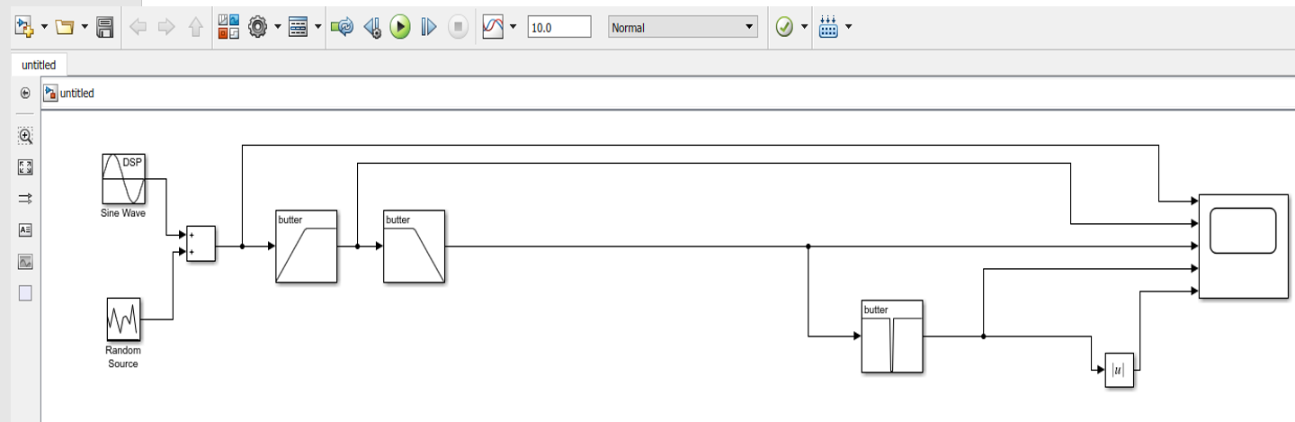
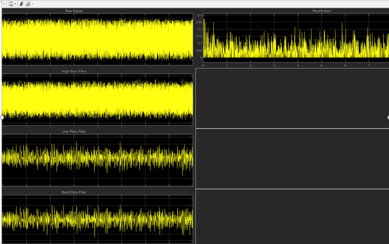
Secondly, I started Extracting the signal and seeing the noise and the disturbance in the signal. Signal was heavily noised, that is why some filters got to be added, so that the EMG signal can be obtained cleanly without any disturbance or noise. Using Matlab, a circuit was created which simply was used to clean the 500 Hz signal obtained from the muscle[6]. The circuit consists of a high pass filter to process the signal after 150 Hz , then a low pass filter , passing the part of the signal which is lower than 350 Hz , then a Bandstop filter which operate from 150 Hz as the lower part and 350 Hz as the upper part just to ensure that there are no ripples at all. Finally , I neglected the negative part of the wave as I only contract the muscle while not relaxing it so I had to cancel out the negative part which represented the opposite moment which is relaxing in this case[7].
Why Did I choose the Matlab ?
The reasons for choosing the Matlab instead of choosing other programs like the Labview for example was because some reasons that were stated by both developers of both programs[8]. To start listing:
- Matlab is simpler in dealing with it’s interface from the Labview.
- Matlab provides Mathematical equation and formulas to help in differentiating between the signal pulses – which was used in coding as the Myoware sensor’s reading were changed to percentage because that made it easier for the code to run and easier for the Matlab to plot the signal – While Labview represent only visual and graphical programming language.
- In using filters, Matlab is pereferd as it contains more libraries for simulation other than the Labview.
Encoding The Signal to the Arduino
The next stage was encoding the signal into code so that the Servo motor would understand that it should turn on once the signal is captured and passes to the microcontroller through the sensor after being filtered.Obviously , the target here is closing the hand.
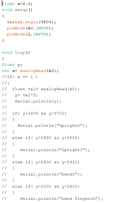
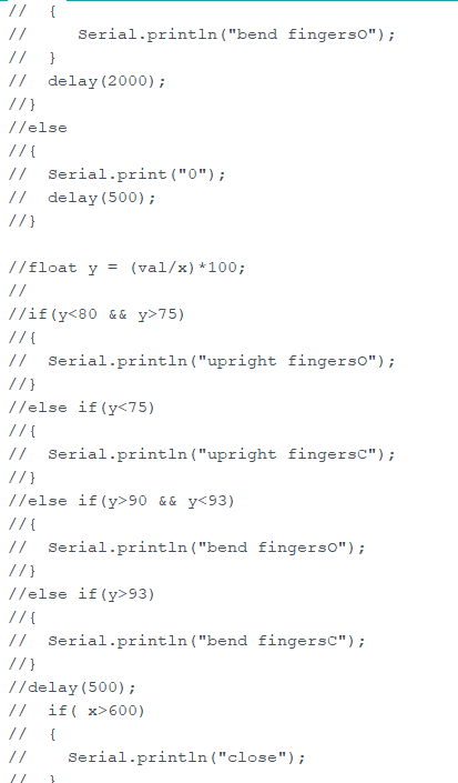
Afterwards, I started writing the Arduino code, it was not a simple task as the difference of readings shown by the serial monitor on the Arduino was not that high to be differentiated , that is why I came up with a brilliant idea! changing the reading into percentage out of the threshold value which is already set on my own arm. In other words, changing the values read by the serial monitor into percentage compared with the highest value that can be read from my own muscle’s contraction to detect weather this is a muscle contraction or relaxation.
float x=0.0;
void setup()
{
  Serial.begin(9600);
  pinMode(A0,INPUT);
  pinMode(2,INPUT);
}

void loop()
{
float y;
int x= analogRead(A0);
//if( x == 1 )
//{
//  float val= analogRead(A0);
//   y= val*5;
//   Serial.println(y);
//
//  if( y<2800 && y>2700)
//  {
//    Serial.println("UprightO");
//  }
//  else if( y>2420 && y<2600)
//  {
//     Serial.println("UptightC");
//  }
//  else if( y>2400 && y<2420)
//  {
//     Serial.println("bendC");
//  }
//  else if( y>2000 && y<2400)
//  {
//     Serial.println("bend fingersO");
//  }
//  delay(2000);
//}
//else
//{
//  Serial.print("0");
//  delay(500);
//}

//float y = (val/x)*100;
//
//if(y<80 && y>75)
//{
//  Serial.println("upright fingersO");
//}
//else if(y<75)
//{
//  Serial.println("upright fingersC");
//}
//else if(y>90 && y<93)
//{
//  Serial.println("bend fingersO");
//}
//else if(y>93)
//{
//  Serial.println("bend fingersC");
//}
//delay(500);
//  if( x>600)
//  {
//    Serial.println("close");
//  }
//  else
//  {
//     Serial.println("open");
//  }
Serial.println(x);
delay(500);
}
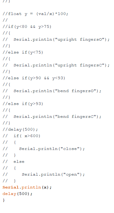
Explaining the code briefly, so I was assigned at the beginning to move the the hand so that it would be in the position of closing or gripping , but this was not enough in my humble perspective, that is why I raised the expectation a little in my code , by setting specific value in which if the reading exceeds it then a specific angle while be produced by the fingers’ motors. To illustrate more , in line 62 I set it that if the value read by the Myoware sensor is more than 600 then the hand will close, that is why it will print the word ” Close. “
Limitations :
- Did not know how to filter the EMG signal becuase I had no background on using the Matlab so I had to watch some tutorials and as some of my friends till I ruled the programme.
Let’s Head to The Elbow !
The elbow part was not easy because as I said previously I was assigned to rotate the elbow ninety degrees before the submission by 2 weeks only , also because my medical condition was not helping at all , and finally and most importantly because till the 19th of August I did not receive any motor for the elbow , although I already reported many times that I needed it.Therefor, I started working on the proof of concept first before any other thing.
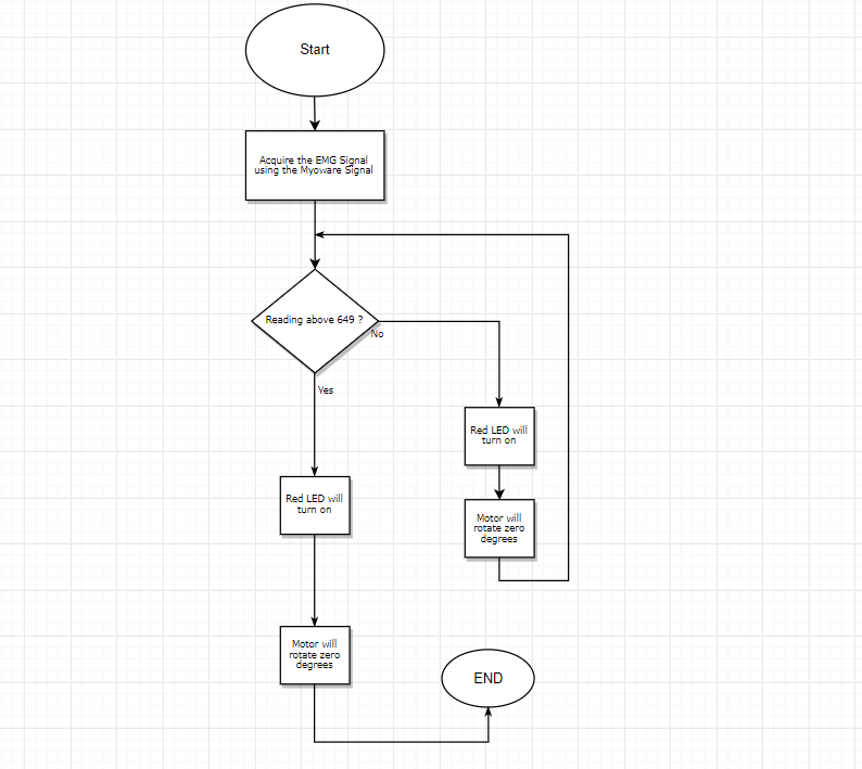
Proof of Concept
To start with, the aim in moving the elbow is rotating the elbow by ninety degrees. Here the Triceps’ and the Biceps’ EMG is extracted using the Myoware and filtered then checked via the Arduino if its above a certien level of activity then the servo motor – LD-20MG – will rotate ninety degrees. However, motor was not recieved until the 19th of August thats why I used 2 LEDs to work as indicators. Illustrating more , a green LED will light up when the Myoware’s sensor is equal or bigger than 649 , meaning that servo will rotate ninety degrees. In addition to another red LED which will light up when the reading is lower than the 649 , meaning that the arm is not contracted. Already I wrote the code of moving the servo by ninety degrees and it is attached with the one of the LEDs but unfortunately there was no servo motor to try it.
#include <Servo.h>

Servo myservo;
int x=0.0;
void setup()
{
  Serial.begin(9600);
  pinMode(5,OUTPUT);
  pinMode(4,OUTPUT);
  pinMode(A1,INPUT);
  myservo.attach(9);
  Serial.println("Start");
  delay(1000);
  x= analogRead(A1);
  Serial.print(x);

}

void loop()
{
  int y= analogRead(A1);
  float z = (y/x)*100;
  if(z<55)
  {
    myservo.write(0);
    digitalWrite(5,HIGH);
    digitalWrite(4,LOW);
    Serial.print("0 Degrees");
  }
  else
  {
    myservo.write(90);
    digitalWrite(4,HIGH);
    digitalWrite(5,LOW);
    Serial.print("90 Degrees");
  }
  Serial.println(y);
  delay(1000);
}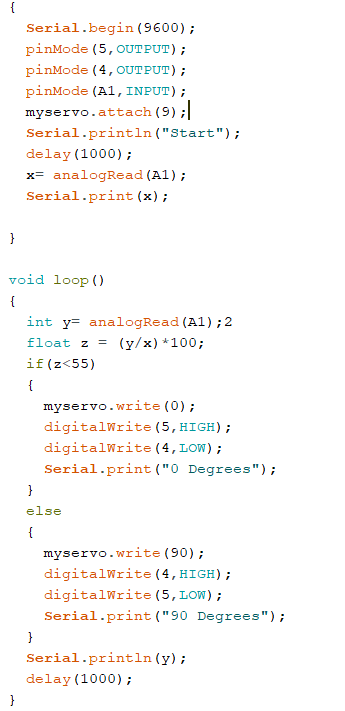
The Elbow’s Code
As I said previously, I did not receive any motors for the elbow, but still I was determined to proof my concept, to proof that the code is working successfully and that it can actually make a motor rotate. Therefore, I decided to try my theory and my code on one of the fingers’ motor. So basically this time it will not be lighting LEDs, it will be rotating the motor by ninety degrees, the moment the muscle contracts – when the value of the muscle reading exceed the maximum value of the contraction which is already mentioned previously –
Wrapping everything up , the code simply illustrates what I said previously , so the value of the reading is obtained from the Myoware sensor then its set as a percentage out of the highest value which is when the muscle is contracted then if the percentage is above a certain percentage then the servo will move by ninety degrees , also the green LED will light up. While, if the percentage is too low then the elbow will not rotate. In other words , the servo will not rotate ninety degrees , it will return to the zero degree , also the red LED will light up.
Elbow’s Limitations:
- Getting assigned to rotate the Elbow so late – 2 weeks before submitting the portfolio –
- Not receiving the servo motor till the 19th of August.
Project’s Limitations
To start with, the project got endless amount of limitations, but I always bieleve that limitations should never make anybody surrender that is why we worked so hard to prove that we can achieve such project.
To list the limitations:
- One of the members quieted all of a sudden , she had her major in communication engineering so her role was significant.
- Catching a bacterial and viral infection, leading in me staying in the quarantine for more than a week, which delayed lots of work for me and for my team members.
- The delay in receiving the motor and the components to the extent that some crucial components will be shared among the team , like the Elbow’s motor which is not logical because the motor need to be impeded deep inside the Elbow itself. Tho we reported many times that we need the components, but the replies were always ” NO ” or ” you buy it .” That is why I did a proof of concept by finishing the code, running it and demoing it on 2 LEDs.
- The finale limitation is that I had no background on Matlab neither processing EMG signals because my major is computer engineering not communication engineering , but I had to takeover the role of the member who quieted that is why it was hard, but as I said previously nothing is impossible that is why I learned Matlab and did the signal processing showing how the Myoware sensor filter the signal.
How the Project can be Upgraded in the future ?
The project can be upgraded and updated in many way. Such project can be even considered a tremendous foundation for other researchers to establish their research and to even use it as a reference later on. There are lots of ways in which such project can be enhanced. To start with, a camera can be embedded in the arm it self to help detect objects in the surrounding area, as amputee at the beginning are not used on having their arm back so a camera got to be embedded to help avoid the arm being hit by anything in the surrounding atmosphere. In addition, a memory card can be added to the arm to save some movements which are crucial , like when people shake hands, already the arm will detect that the guy in front of you want to shake his hand with you so automatically the arm will help you to raise it and to shake your hand with his hand. Moreover , solar panels can be attached on the surface of the arm so that we totally eliminate the need of power supplies for the servo, while attaching a 16×2 LCD which can tune the user about the charging of the arm. Furthermore, the project can be used in nanotechnology, by establishing a connection to the neural network in which the arm will be connected directly to our nervous system via the neurons in our antagonistic pair of muscles in our arm so that the arm act as if its a living limb in our body , even getting the commands from our nervous system since it will connected to it. In addition to adding an artificial intelligence program inside the arm which detect if a maintenance should be done and detect if there are some problems in the mechanical system or even in the software and interface systems as it is not that simple to remove the arm and to completely de-assemble it every time just to do maintenance. A further point, with the presence of a medical team, tests can be done by injecting the human’s muscle with the chemical mentioned previously to help in differentiating the signal produced for each finger in moving the fingers, which can then be used in machine learning. Lastly, the signal processing and the signal filtration that was documented can be used in further researches on the EMG signal to help in developing and manufacturing other robotic limbs.
Conclusions
To wrap up, Humans’ limbs and specially our hands, are one of our main and primary organs which we can not live normally without. As a consequence, the prosthetic arm got to meet all the amputee’s starting from hands’ signature to how it grips and helps in eating and every other thing. That is why the Robotic Arm should meet all the amputee’s requirement so that the amputee feels as if the real hand is back and that the amputee got no disability at all.
Reflection
At the beginning of the project, things seemed to be complicated and indeed they were. Intensive work and researches solved everything thing , they were the keys for me to understand how to possess the EMG signal and how to control the servo motor because as I said previously , I had no background about the EMG, which was a reason for me to learn Matlab. As a consequence, I filtered the signal and even possessed it via the Arduino and controlled the Servo’s rotational angle using it.
References
[1] Panagiotis K. Artemiadis and Kostas J. Kyriakopoulos; A Switching Regime Model for the EMG-Based Control of a Robot Arm, IEEE TRANSACTIONS ON SYSTEMS, MAN, AND CYBERNETICS—PART B: CYBERNETICS, VOL. 41, NO. 1, FEBRUARY 2011.
[2] Yamik Mangukiya, Brij Purohit and Kiran George; Electromyography(EMG) sensor controlled Assistive Orthotic Robotic Arm for Forearm Movement, IEEE Instrumentation and Measurement Society.
[3] LUDOVICO MINATI, NATSUE YOSHIMURA4, AND YASUHARU KOIKE4; Hybrid Control of a Vision-Guided Robot Arm by EOG, EMG, EEG Biosignals and Head Movement Acquired via a Consumer-Grade Wearable Device, Received December 22, 2016, accepted January 1, 2017, date of publication January 4, 2017, date of current version January 27, 2017.
[4] M. Hidalgo, G. Tene, and A. Sainchez; Fuzzy Control of a Robotic Arm using EMG Signals, *Departamento de Automatizacion y Control Industrial, Escuela Politecnica Nacional.
[5] Minas V. Liarokapis, Panagiotis K. Artemiadis, Pantelis T. Katsiaris and Kostas J. Kyriakopoulos; Learning Task-Specific Models for Reach to Grasp Movements: Towards EMG-based Teleoperation of Robotic Arm-Hand Systems, The Fourth IEEE RAS/EMBS International Conference on Biomedical Robotics and Biomechatronics Roma, Italy. June 24-27, 2012
[6Minas V. Liarokapis, Panagiotis K. Artemiadis, Pantelis T. Katsiaris Kostas J. Kyriakopoulos and Elias S. Manolakos; Learning Human Reach-to-Grasp Strategies: Towards EMG-based Control of Robotic Arm-Hand Systems, 2012 IEEE International Conference on Robotics and Automation RiverCentre, Saint Paul, Minnesota, USA May 14-18, 2012.
[7] J.S. Artal-Sevil, A. Acón, J.L. Montañés and J.A. Domínguez.; Design of a Low-Cost Robotic Arm controlled by Surface EMG Sensors, Research (PIIDUZ 2017/18). Project Reference: PIIDUZ_17_059, University of Zaragoza
[8] What Is the Difference Between LabVIEW and MATLAB? . Electronics For You. 2018 . Available from: https://electronicsforu.com/resources/learn-electronics/difference-between-labview-and-matlab
